E-mail:
Email1Call Us:
+8613758165819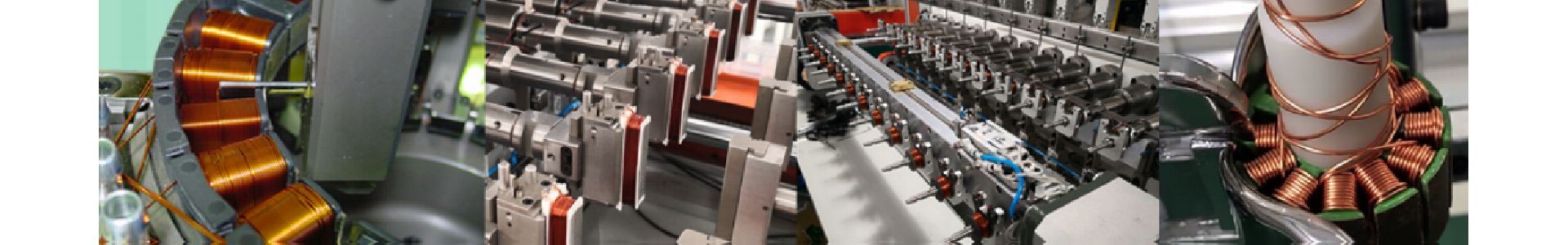
In electrical engineering, coil winding is the manufacture of electromagnetic coils. Coils are used as components of circuits, and to provide the magnetic field of motors, transformers, and generators, and in the manufacture of loudspeakers and microphones. The shape and dimensions of a winding are designed to fulfill the particular purpose. Parameters such as inductance, Q factor, insulation strength, and strength of the desired magnetic field greatly influence the design of coil windings. Coil winding can be structured into several groups regarding the type and geometry of the wound coil. Mass production of electromagnetic coils relies on automated machinery.
In the linear winding method, a winding is produced by winding the wire onto a rotating coil body, component or coil carrying or coil forming device. The wire is pulled from a supply roll that contains 400 kg of enamelled copper wire. The wire is fed through a guiding tube. Before starting the actual winding process, the wire is mounted to a post or a clamping device of the coil body or winding device.
By the linear laying movement of the wire guiding tube, the component to be wound is turned in a way that the wire is distributed throughout the winding space of the coil body. The rotary motion as well as the laying movement is achieved by using computer controlled motors. In relation to one rotation of the rotation axis and depending on the wire diameter, the traversing axis of the wire guiding tube is moved accordingly (traverse pitch).
In doing so, rotational speeds of up to 30,000 1/min can be reached, especially when processing thin wires. Depending on the winding diameter, wire speeds of up to 30 m/s are achieved during the winding process. The components to be wound are mounted on winding devices. The winding devices are coupled with driven spindles that generate the turning motion. Since bringing the wire into the winding area should be done as evenly as possible, the rotational axis and the traversing axis operate synchronously during the winding process.
In order to be able to control the positions of the wire guiding nozzle in relation to the component to be wound, even with different component geometries, normally three CNC axes are used for the method with a wire guiding nozzle.
This enables the terminating to coil body posts (the posts are also intended to make contacts by soldering or welding): By letting the three axes run in a way that a spiral movement of the wire guiding nozzle around the initial winding post results, it is possible to fix the start or end wire of a coil by the termination. To keep the wire taught when changing the product, it is fixed to a wire parking pin of the machine.
This wire parking pin can either be a clamp or a copy of a post that is wrapped at the coil similar to the termination process. Before the winding starts and after terminating the start wire post, the wire to the parking pin needs to be cut. This takes place according to the wire thickness by tearing or cutting.
Enamelled copper wires up to a diameter of approx. 0.3 mm can be torn normally by a tearing pen that passes close to the post of the coil or the wire guiding nozzle itself. The separating point should be very close to the post of the coil in order not to impede a subsequent contacting process (soldering, welding etc.).
Since all the movements during winding are directed via CNC axes, it is possible to achieve wild windings, orthocyclic windings or other winding geometries (e.g. cross-coils). The wire guiding control can often be switched between continuous and gradual movement.
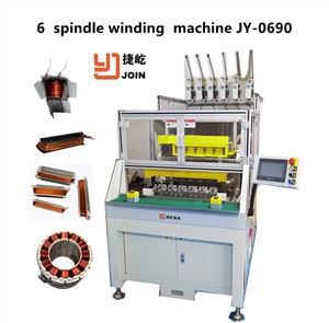
Owing to the separation between wire guiding and rotation of the component to be wound, the configuration of product and wire guiding can be duplicated in the linear winding technology. Therefore, it is possible, e.g., to wind onto 20 spindles simultaneously. This makes the linear winding method a very efficient process since the cycle time for producing a component results from the quotient of the winding process cycle time and the number of used spindles. The linear winding technology is often applied efficiently where low-mass coil bodies have to be wound.
Flyer winding
In the flyer winding method, a winding is produced by feeding the wire via a roll or through a nozzle that is attached to a flyer that is rotating at a certain
distance from the coil. The wire is fed by the flyer shaft. For winding the component to be wound, it needs to be fixed inside the winding area of the flyer. It is necessary that the wire is fixed outside of the flyer at any time of the winding procedure. The fixation of the wire is made possible normally by the successive winding method (often used at rotary indexing tables): At the circumference of the table are wire clips or wire deflections that enable a pulling along and with it a fixation of the wire. This will allow a very quick component change, given that no separate depositing of the wire in a wire clip on the machine is required.
Because the last guided point of the wire is located at a nozzle or roll of a flyer arm which is moving on a fixed circular path that can only be shifted in laying direction, a precise laying close to the coil surface is impossible. As a result, it is not easily possible to clearly lay down or even to terminate the start and end wires onto the component to be wound. But it is certainly possible to produce also orthocyclic coils with the flyer winding process. Here, a self-guiding behavior of the wire on the coil surface is an advantage.
As the component to be wound has to be presented only in the winding position and otherwise does not need to perform any movement during the winding process, also very bulky and massive products can be manufactured. One example is the rotors of electric motors (rotor winding technology, special form of the successive winding method): The wire is held by a clip fixed to the machine during the component change. Since the rotors often consist of heavy, punch-packed metal sheets, the flyer winding technology is of particular advantage in this regard. Since the flyer cannot be directly guided in case of the rotor winding technology, the wire is guided across polished guiding blocks into the corresponding groove or slot. Special wiring sleeves ensure the correct wire position at the terminals of the Commutators.x
Needle winding technology
To efficiently wind the pole shoes lying close together of electronically commutated multipole three-phase motors, they will be coated with insulation and directly wound with the needle winding method. A needle with a nozzle that is placed at a right angle to the direction of movement travels in a lifting motion passing the stator packs through the groove channel between the two neighboring poles of the motor to drop the wire in the desired place. The stator is then turned at the reversal point on the winding head by one tooth pitch so that the previous process can run again in reverse order. With this winding technology a specific layer structure can be realized. The disadvantage is that there must be a clearance between two adjacent poles with a size of at least the nozzle diameter. The nozzle diameter is about three times the diameter of the winding wire. The space between two adjacent poles can therefore not be filled completely.
An advantage of the needle winding technology is the fact that the needle support carrying the wire guiding nozzle is normally coupled to a CNC coordinate system. This allows moving the nozzle through space towards the stator. This way, it is possible to also perform a laying movement apart from the normal lifting motion and the rotation of the stator. A targeted placing of the wire is nevertheless only possible to a limited extend since the wire is pulled at an angle of 90° from the wire guiding nozzle resulting in an undefined bulging.
The 90° redirection of the wire when exiting the hollow needle stresses the wire a lot and makes it difficult to wind copper wires with a diameter of more than 1 mm in a reasonable way. Orthocyclic winding with a needle winder is therefore only partly possible for these winding tasks.
Since the wire guiding nozzle can be moved freely throughout the room, it is possible for the nozzle to terminate the wire at the contact points if equipped with an additional swivel device. As in the case of the conventional linear winding technology, a contact pin or a hook contact can be terminated for the electrical connection and for interconnecting the single poles in a star connection or delta connection.
With the toroidal core winding technology an electric coil or winding is created by winding an electrical conductor (e.g. copper wire) through the circular ring and evenly distributing it over the circumference (Toroidal inductors and transformers, toroidal chokes).
Before the winding starts, the Toroidal / Magnetic core is mounted into a holding fixture that can initiate a slow rotary movement of the core with mostly three rubberized points of contact. A wire storage ring (orbital wheel) arranged 90° to the toroidal core will now be opened at the circumference and introduced into the center of the toroidal core. The wire is then coiled around the wire storage ring that was closed again. When the required amount is present on the wire accumulator, the end of the wire from the wire accumulator is fixed to the toroidal core that needs to be wound. By simultaneous rotation of the toroidal core and the wire accumulator ring, a winding develops that is distributed along the circumference of the toroidal core. Upon completion, the wire accumulator has to be opened again in order to be able to remove the ready wound toroidal core. Since the start and end wire are often not fixable to the toroidal core, toroidal winding machines can only be partly automated.
Toroidal cores are used despite the high manufacturing costs (a great deal of manual work) due to the low magnetic flux leakage (MFL – Leakage inductance), low core losses and the good power density. One possible quality feature of transformers is a uniform distribution of the windings along the circumference (low stray field). The insulation between the various windings can be solved quite differently. In case of covering windings, a film is applied after the first winding to achieve good stray field characteristics. This film needs to be wound to cover the whole circumference. For this, also toroidal winding machines with special magazines can be used.